Panel Tag Co · specification guide
Metric dimensions and existing mounting holes
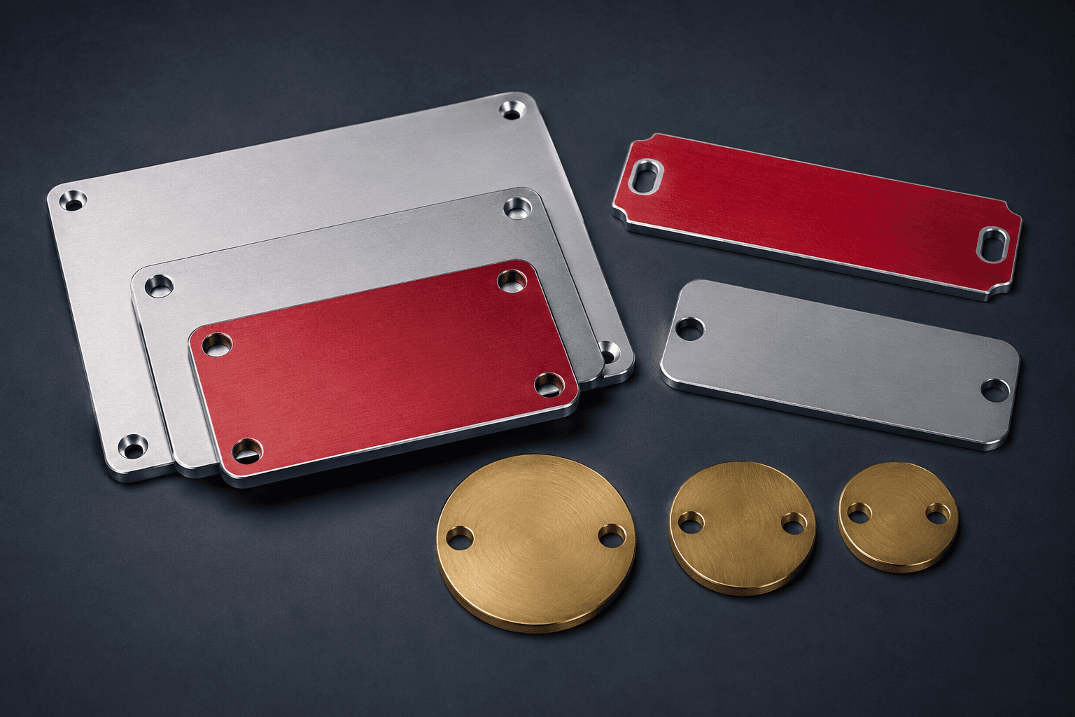
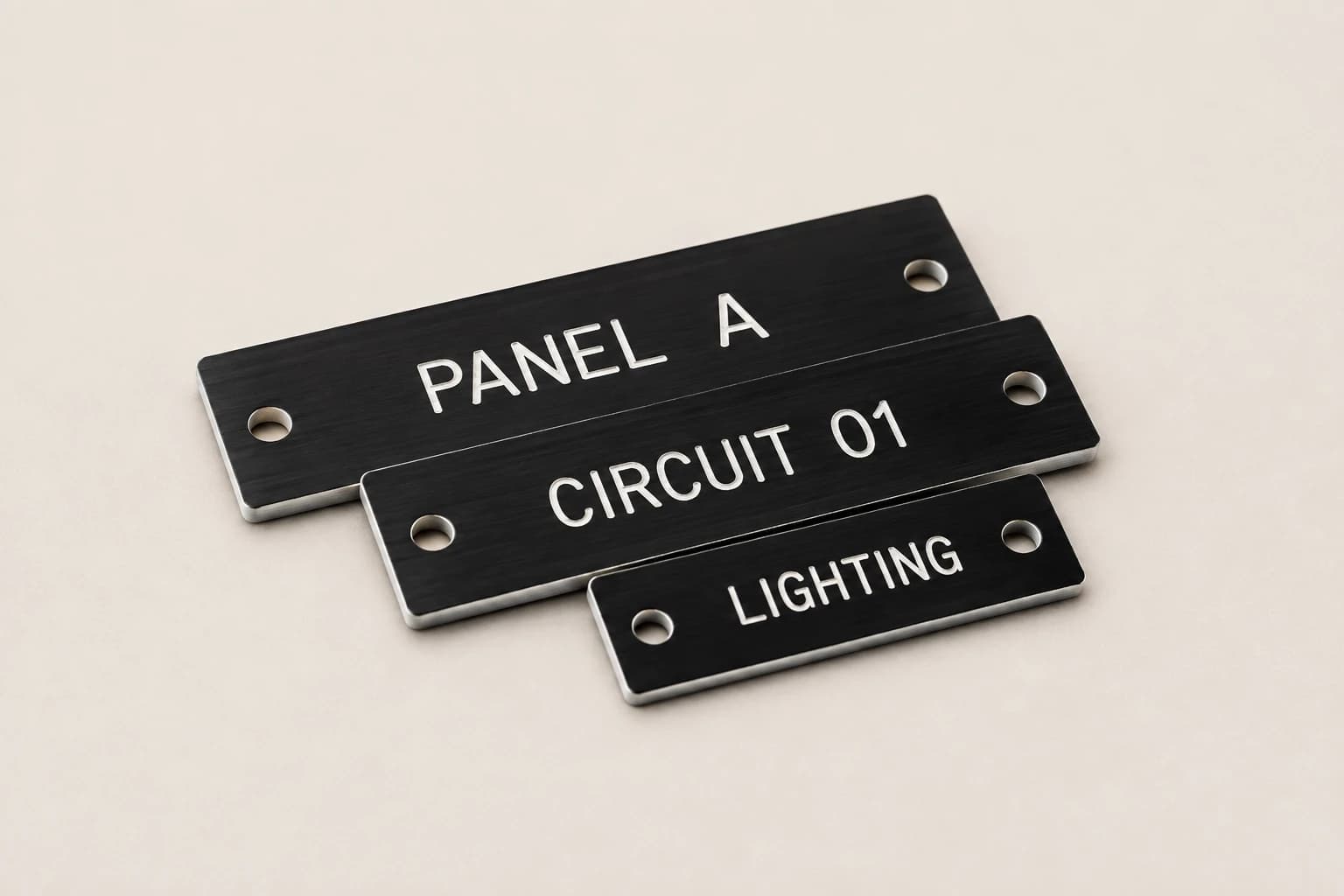
For a replacement plate, send the overall dimensions and a drawing that locates every mounting feature from clearly defined references. State the units, thickness, hole diameter or slot dimensions, front-view orientation and which measurements come from an approved drawing versus an existing sample. A plate can have the correct outside width and still fail to match the intended mounting pattern.
Reviewed 2026-09-05 · AI-assisted editorial review. General buying guidance; illustrative scenarios are not customer case studies. Images are AI-generated concepts.
Keep one authoritative dimension set. If you include converted measurements, label them as reference values and identify which units govern the drawing. Conversion changes how a length is expressed; it does not make a rough field measurement exact or establish the tolerance a manufacturer can achieve. Resolve uncertain dimensions before releasing a replacement whose fit depends on existing holes.
Separate exact conversion from the accuracy of the source
NIST states that one inch is exactly equivalent to 25.4 millimeters. Using that relationship, multiply an inch measurement by 25.4 to express it in millimeters, or divide millimeters by 25.4 to express it in inches. Keep the original measurement and its unit alongside any derived value.
An exact conversion factor does not mean the source measurement was exact. A dimension estimated from a photograph remains an estimate after conversion. A reading taken from a worn sample may need confirmation against the actual approved mounting arrangement. Do not add decimal places to make an uncertain measurement appear suitable for production.
When several people supply measurements, ask them to identify the reference they used. Width may mean the complete plate, the visible area inside a frame, or the distance between mounting features. Those are different lengths. A labeled sketch or drawing is more useful than a bare number sent in a message, especially when the item must match something already installed.
Sources: National Institute of Standards and Technology: SI Units – Length
Choose a view and a repeatable measuring reference
A simple dimensioned front view can identify the plate's left edge, lower edge and visible face. Locate hole centers from those references, or provide another clear dimensioning convention agreed with production. State whether a drawing shows the finished front or the reverse. A mirrored hole pattern can look plausible until someone tries to align an asymmetric part.
Distinguish center-to-center spacing from the clear gap between hole edges. If the measurement was taken between edges, record that fact and the hole sizes rather than silently relabeling it as a center distance. Ask the drawing owner or production team to resolve the geometry. The goal is a reproducible specification, not a collection of numbers whose relationship must be guessed.
Use a stable reference for every feature. For two holes, H1 and H2 can identify their positions and dimensions. For slots, specify the orientation and agreed overall geometry rather than writing elongated hole with no dimensions. Add corner or edge details where they affect fit. A sketch may begin the conversation, but the released drawing needs to describe the actual construction that is being approved.
Illustrative example: a two-hole replacement plate
Consider a fictional front-view drawing for a plate 4.000 inches wide and 2.000 inches high. Its two hole centers are at x = 0.500 and x = 3.500 inches, both at y = 1.000 inch, measured from the left and lower edges. Each hole is specified as 0.125 inch in diameter. These are example drawing values, not measurements or tolerances for an actual installation.
The metric reference values are 101.6 millimeters wide and 50.8 millimeters high. The center coordinates become x = 12.7 and x = 88.9 millimeters, both at y = 25.4 millimeters. The center-to-center spacing is 3.000 inches, equivalent to 76.2 millimeters, and the stated hole diameter converts to 3.175 millimeters. The downloadable file preserves the original inch dimensions and labels the millimeter values as derived references.
If a second note calls for 75 millimeters between centers, that conflicts with the example drawing's 76.2-millimeter spacing. Do not average the numbers or choose the one that seems easier to produce. Ask the responsible source owner which dimension applies and revise the drawing accordingly. A corrected label cannot solve contradictory geometry.
The accompanying quantity example is separate: eight plates using this proposed pattern, with no extra copies. Its result is eight physical pieces. The calculator does not check the drawing, convert dimensions or approve fit. Use it to keep the requested quantity explicit while the dimensioned drawing carries the geometry.
Evidence for a replacement serves different purposes
Choose the grouping that answers the purchasing question; keep the other references in the schedule.
| Option | What it counts or controls | What it does not establish |
|---|---|---|
| Approved drawing | Defines the intended geometry in stated units and a known revision. | That an old installed part still matches the drawing. |
| Existing sample | Shows a physical object available for comparison. | Whether wear, bending or an earlier modification should be reproduced. |
| Dimensioned photograph | Can explain which feature was measured and its context. | Reliable scale or fit from the image alone. |
| Converted dimension list | Expresses the source lengths in another unit system. | Extra accuracy, accepted tolerances or available stock sizes. |
| Fit check against an approved template | Checks the proposed geometry against the agreed reference. | Authorization for installation or suitability of the entire equipment assembly. |
Reconcile the physical pieces in this example
Load the illustrative article example, then replace each group and quantity with your approved order. Keep exact identifiers and specifications in the separate schedule.
Method: Multiply each row count by copies per group, then add only explicitly entered spares. This is an inventory calculation, not an engineering or compliance review.
Build your plan
Use one row per tag type. For example: Valve labels | 20 | 2. Material, dimensions, legend text and mounting belong in the final tag schedule.
Use the article’s example files
This is a fictional planning example. Import identifier columns as text and replace sample rows with authorized project data before requesting production.
Ask for achievable tolerances before approving critical fit
A drawing should identify which dimensions matter to the fit and request confirmation of the tolerances needed for those features. Do not assume that all fabrication methods or materials share one default accuracy. Ask production to confirm the proposed process, measurable acceptance criteria and any drawing detail that needs clarification before quoting a fit-dependent replacement.
Avoid substituting a nearby nominal size without approval. A converted hole diameter is not automatically the same as an available drill size, fastener designation or clearance recommendation. Those choices depend on the approved design. If production proposes a practical alternative, record the revised geometry and have the responsible project reviewer accept it before work begins.
The same care applies to thickness, countersinks, recesses and the space around mounting features. These may affect the final assembly even if the plate's outline looks unchanged. State what must match the existing specification and what can be redesigned. This gives production room to propose a suitable solution without treating every visible detail as either mandatory or irrelevant by default.
Review the engraving and mounting layout together
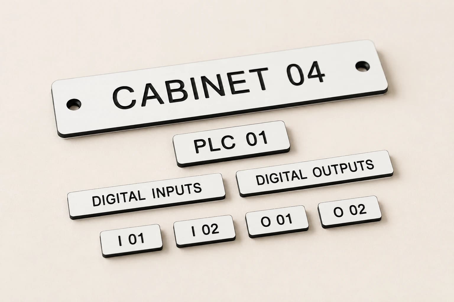
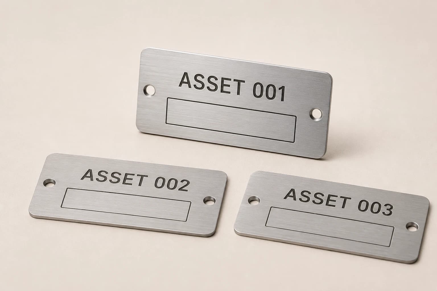
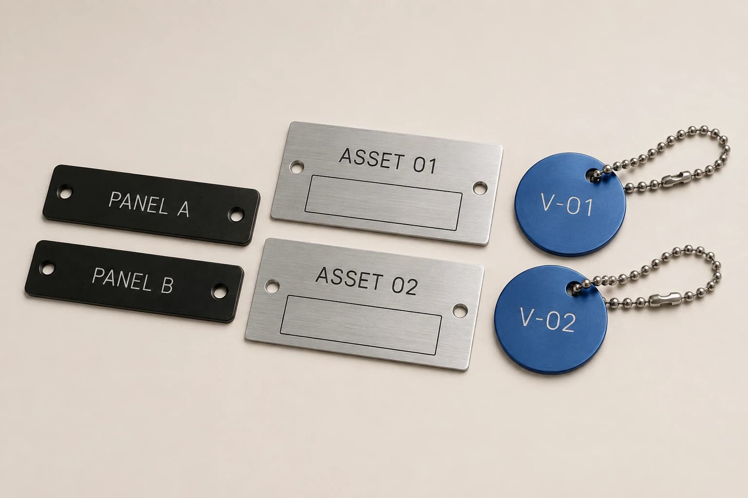
Place the approved inscription on the same proposed front view that shows mounting features and the outer shape. A text proof without hole locations may hide a conflict between lettering and the mounting arrangement. A geometric drawing without the intended wording may leave too little usable area for the approved legend. Review both layers as one finished plate layout.
Confirm how the plate should be read once mounted. An asymmetric pattern, a directional mark or a particular edge alignment can determine orientation. Make that orientation explicit in the drawing and packing reference. Do not rely on the production operator interpreting a photograph in the same way as the person who took it.
For several related plate sizes, give each format its own reference and link every inscription row to the correct format. Reusing a short legend does not justify reusing the same plate geometry. A drawing register with format, revision, governing units and approved use keeps a mixed replacement order understandable when it reaches artwork, fabrication and receiving.
Resolve the source before making an irreversible part
If the original drawing is unavailable, describe the evidence you can provide and ask what additional information is needed. An accessible spare plate, a manufacturer drawing or measurements collected by an authorized person may support a proposed replacement. Do not remove covers, approach live equipment or alter an installation merely to obtain a better photograph for a quote. Arrange any site work through the responsible team.
A physical template or sample can be useful when the pattern is unusual, but agree what it represents. Is the sample the intended design, a damaged object to be corrected, or only an outline reference? Mark features that should repeat and features that need redesign. Otherwise, reproducing an old defect accurately may still produce the wrong replacement.
At release, identify the final drawing revision, exact inscription schedule, physical quantity and any approved deviations. Keep obsolete measurements in the project history, clearly superseded, rather than leaving two competing files in the active order folder. The next person should be able to find one authoritative instruction without reconstructing a long email chain.
Questions before ordering
Can you work from millimeter dimensions?
Include the dimensions in their original units and identify the governing drawing. Any conversion should be labeled as a reference. Production still needs to confirm the design, process and achievable tolerances for the actual plate.
Is the distance between hole edges enough?
It may help describe a measurement, but identify exactly which edges and supply the hole dimensions. Do not relabel an edge gap as a center distance. Resolve the complete geometry in the approved drawing.
Can a photo establish the replacement size?
A photograph can explain appearance and context. It should not be the sole basis for fit-dependent dimensions unless an agreed measurement process establishes them. Send a dimensioned drawing or ask what additional evidence is needed.
Does a converted value specify the fastener?
No. A length conversion does not select a fastener, clearance, hole tolerance or installation method. Those choices belong in the approved assembly specification.
Explore the collection’s design direction
This existing narrated collection overview introduces the product designs. It provides visual background; the specific decision, comparison and worked example are in the article above. Images are original concepts rather than completed customer orders.
25-second overview
Define the installation
Before changing a tag material, identify what cannot change: the legend, mounting pattern, exposure and project requirements. Compare complete options, preserve identifiers in a controlled file, and review the longest text at the proposed size. Keep the approved drawing with the order record. Use the tag calculator to prepare quantities for your quote.
Prepare your brief and request a written quote.
Bring this decision into your design brief
Choose a relevant product direction and include the measurements, quantity, approved wording and delivery destination for your project. We can then develop a specific design and quote around those requirements.
Sources and scope
The sources below support the cited technical details. The ordering workflows are editorial recommendations. Your project specification, price and schedule are established in the written quote and approved proof.
- National Institute of Standards and Technology: SI Units – Length · checked 2026-09-05
Which buying guide should you read next?
All buying guidesCompares two published facility electrical identification specifications side by side to show that nameplate colors differ by owner, then lists exactly what to send so engraved tags match your own specification. Panel Tag Co engraves to the specification you supply and makes no code-compliance claim.
Protect the exact identifier through spreadsheet import, export, proof and packing while separating engraving text from quantities and refusing to reconstruct lost digits without an authoritative schedule.
Count unique legends, physical copies and installation kits separately. Preserve identifiers as text and attach the approved drawing revision, dimensions and mounting detail to each group. Split the packing schedule by panel or site without changing the source identifiers.
Group labels by the cabinet or work stage they belong to, with a contents list that makes each kit easy to receive, issue and replace.